
EV Blocks Stability Calculator
Primary Inputs
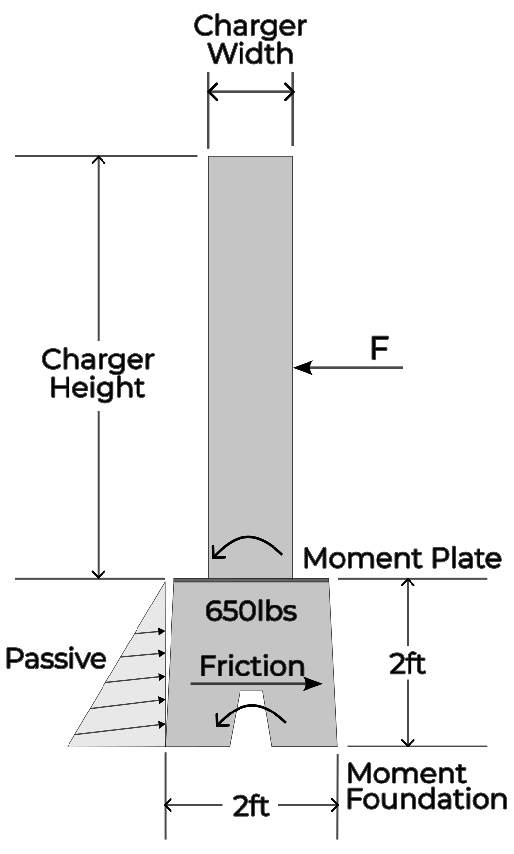
Plate
Overturning Moment on Adaptor Plate, Mop =
Adaptor Plate Moment Capacity, Mrp =
Adaptor Plate Connection Results
Base
Overturning Moment on Foundation, Mob =
Resisting Moment from Weight, Mrw =
Resisting Moment from Passive Pressure, Mrp =
Resisting Moment from Side Friction, Mrsf =
Total Resisting Moment, Mrt =
Foundation Overturning Factor of Safety, FoS =
Final design and construction, for a specific application of EV Blocks, is the sole responsibility
of the user. Anyone making use of this calculation does so at their own risk and assumes any and
all liability resulting from such use.
All calculations should be performed or reviewed by a qualified Professional Engineer prior to
EV Block foundation installation. A qualified Engineer is one that is familiar with the site conditions,
project information, soil mechanics and the design theory presented in this calculation
The Precast Forte Group (partnered with UK based EV Block, Ltd.), disclaims any and all expressed or implied
warranties of merchantability or fitness for a particular purpose with regard to any and all use of
this calculation with regard to any information or products contained or referred to herein.
Page 1 of 4
Calculation Steps
Step 1 - Determine Wind Pressure
qz = 0.00256*Kz*Kzt*Kd*V^2
Kz =
Kzt =
Kd =
V =
qz =
Step 2 - Determine Wind Force
F = qz*G*Cf*As
qz =
G =
Cf =
As =
F =
Step 3 - Determine Overturning Moment on Plate
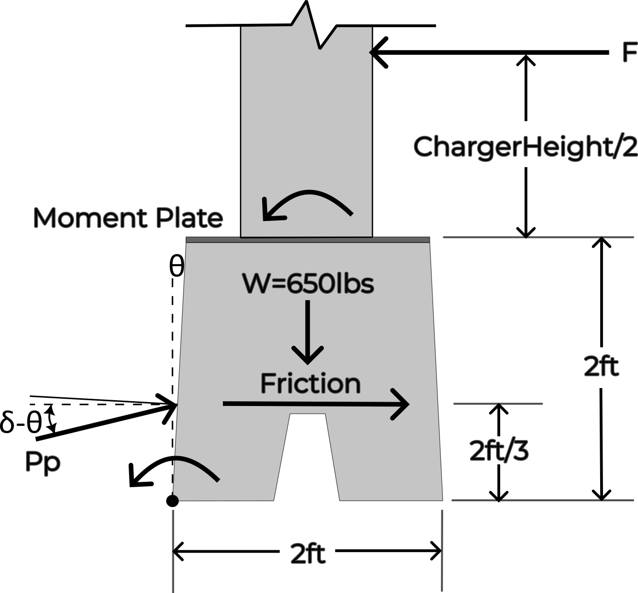
Plate Mo = F*0.5Hc
Hc = Height of Charger (in feet)
Plate Mo =
Step 4 - Check Adaptor Plate Connection Capacity
Ult. Moment Cap. on plate connection =
Allow. Moment Cap. on plate connection =
Plate Connection Check
Final design and construction, for a specific application of EV Blocks, is the sole responsibility
of the user. Anyone making use of this calculation does so at their own risk and assumes any and
all liability resulting from such use.
All calculations should be performed or reviewed by a qualified Professional Engineer prior to
EV Block foundation installation. A qualified Engineer is one that is familiar with the site conditions,
project information, soil mechanics and the design theory presented in this calculation
The Precast Forte Group (partnered with UK based EV Block, Ltd.), disclaims any and all expressed or implied
warranties of merchantability or fitness for a particular purpose with regard to any and all use of
this calculation with regard to any information or products contained or referred to herein.
Page 2 of 4
Step 5 - Foundation Overturning Moment
Foundation Mo = F*(0.5Hc + Hb)
Foundation Mo =
Step 6 - Foundation & Charger Resisting Moment from Weight
Weight Mr = (Wf + Wc)*(L2/2)
where
L2 = Db + 2*[Hb*tan(draft)] (Db = Depth of Base, Hb = Height of Base)
L2 =
Weight Mr =
Step 7 - Foundation Resisting Moment from Passive Pressure
Pp = 0.5*Kp*SoilDensity*Hb^2
Note: for X-dir multiply Pp times cos(delta-theta), for Y-dir multiply Pp times sin(delta-theta)

Soil Friction Angle = phi =
Draft Angle = theta
Angle of Friction = delta = 2/3(phi) =
Backslope Angle = alpha =
Passive Earth Pressure Coefficient = Kp =
Soil Density =
Hb =
Pph =
Ppv =
y-arm =
x-arm =
L1 = (foundation length at Hb/3)
Passive Mr = L1*Pph*y-arm - L1*Ppv*x-arm
Passive Mr =
Step 8 - Foundation Resisting Moment from Side Friction
Po = 0.5*Ko*SoilDensity*Hb^2*tan(phi)
At-Rest Earth Pressure Coeff
Ko = 1 - sin(phi) =
Po =
Side Friction Mr = 2*Po*L1*y-arm
Side Friction Mr =
Step 9 - Foundation Overturning FoS
Total Foundation Mr = Weight Mr + Passive Mr + Side Friction Mr
Total Foundation Mr =
Foundation Mo =
Foundation Overturning FoS =
Final design and construction, for a specific application of EV Blocks, is the sole responsibility
of the user. Anyone making use of this calculation does so at their own risk and assumes any and
all liability resulting from such use.
All calculations should be performed or reviewed by a qualified Professional Engineer prior to
EV Block foundation installation. A qualified Engineer is one that is familiar with the site conditions,
project information, soil mechanics and the design theory presented in this calculation
The Precast Forte Group (partnered with UK based EV Block, Ltd.), disclaims any and all expressed or implied
warranties of merchantability or fitness for a particular purpose with regard to any and all use of
this calculation with regard to any information or products contained or referred to herein.
Page 3 of 4
References and Tables
ASCE/SEI 7 Minimum Design Loads for Building and Other Structures, American Society of Civil
Engineers / Structural Engineering Institute - Current Edition
Wind Exposure Categories (ASCE 7)
| B | Urban and suburban areas, wooded areas, or other terrain with numerous closely spaced obstructions having the size of a single-family dwelling or larger, prevailing for a distance greater than 1500 feet in any direction from the installation. |
|---|---|
| C | Open terrain with scattered obstructions haveing heights generally less than 30 feet. (commonly associated with flat open areas and areas not meeting the requirements of categories B or D) |
| D | Areas located a close distance (typically within 600 feet) from an "open waterway" one mile or more across. This category is readily distinguishable, where the locally enforced code very likely has this listed in the requirements. |
Velocity Pressure Exposure Coefficient, Kz (ASCE 7 Section 29.3.1)
| Height Above Ground Level, z | Exposure | |||
|---|---|---|---|---|
| B | C | D | ||
| ft | (m) | |||
| 0 - 15 | (0 - 4.6) | 0.57 | 0.85 | 1.03 |
| 20 | (6.1) | 0.62 | 0.90 | 1.08 |
| 25 | (7.6) | 0.66 | 0.94 | 1.12 |
Wind Directionality Factor, Kd (ASCE 7 Section 26.6)
| Chimneys, Tanks, and Similiar Structures | |
|---|---|
| Square | 0.90 |
| Hexagonal | 0.95 |
| Round | 0.95 |
Topographic Factor, Kzt (ASCE 7 Section 26.8.2)
If site conditions and locations of structures do not meet all the conditions specified in Section 26.8.1 then Kzt=1.0.
Velocity Pressure, qz (ASCE 7 Equation 29.3-1)
qz = 0.00256 Kz Kzt Kd V^2 (lb/sf)
Gust-Effect Factor, G (ASCE 7 Section 26.9)
26.9.1 Gust-Effect Factor: The gust factor for a rigid building or other structure is permitted to be taken as 0.85.
Force Coefficient, Cf (ASCE 7 Figure 29.5.1)
| Cross-Section | Type of Surface | h/D | ||
|---|---|---|---|---|
| 1 | 7 | 25 | ||
| Square (wind normal to face) | All | 1.3 | 1.4 | 2.0 |
| Square (wind along diagonal) | All | 1.0 | 1.1 | 1.5 |
| Hexagonal or Octagonal | All | 1.0 | 1.2 | 1.4 |
| Round ( Dsqrt(qz) > 2.5 ) or ( Dsqrt(qz) > 5.3 in m, qz in N/m ) | Moderately smooth | 0.5 | 0.6 | 0.7 |
| Rough (D'/D = 0.02) | 0.7 | 0.8 | 0.9 | |
| Very rough (D'/D = 0.08) | 0.8 | 1.0 | 1.2 | |
| Round ( Dsqrt(qz) <= 2.5 ) or ( Dsqrt(qz) <= 5.3 in m, qz in N/m ) | All | 0.7 | 0.8 | All |
Design Wind Force, F (ASCE 7 Equation 29.5-1) F = qz G Cf Af (lb) (N)
Page 4 of 4